Friday, August 9, 2024

Cisco ASR1001-X Throughput License

The Cisco ASR1001-X Throughput license is an honor-based license. Meaning, there's no need to purchase the 20 Gbps Throughput Product Activation Key (PAK) license. Just simply activate it, accept the End User License Agreement (EULA) and reload the router to take effect.

Cisco IOS XE Software feature licenses

    Certain functions supported on the Cisco ASR 1000 Series require feature licenses.

    All Cisco ASR 1000 feature and performance upgrade licenses are honor-based; that is, they are not enforced through a Product Activation Key (PAK). Note: Prior to Cisco IOS XE Software Release 3.7S, performance upgrade licenses that are required to upgrade the Cisco ASR 1001 from 2.5 to 5 Gbps or the Cisco ASR 1002-X from 5 to 10 to 20 to 36 Gbps are enforced through a PAK. Similarly, prior to Cisco IOS XE Software Release 3.6S, technology package licenses are enforced through a PAK.


ASR1K#configure terminal

Enter configuration commands, one per line.  End with CNTL/Z.

ASR1K(config)#platform hardware throughput level 20000000

         Feature Name:throughput_20g

 
PLEASE  READ THE  FOLLOWING TERMS  CAREFULLY. INSTALLING THE LICENSE OR
LICENSE  KEY  PROVIDED FOR  ANY CISCO  PRODUCT  FEATURE  OR  USING SUCH
PRODUCT  FEATURE  CONSTITUTES  YOUR  FULL ACCEPTANCE  OF  THE FOLLOWING
TERMS. YOU MUST NOT PROCEED FURTHER IF YOU ARE NOT WILLING TO  BE BOUND
BY ALL THE TERMS SET FORTH HEREIN.

Use of this product feature requires  an additional license from Cisco,
together with an additional  payment.  You may use this product feature
on an evaluation basis, without payment to Cisco, for 60 days. Your use
of the  product,  including  during the 60 day  evaluation  period,  is
subject to the Cisco end user license agreement
http://www.cisco.com/en/US/docs/general/warranty/English/EU1KEN_.html
If you use the product feature beyond the 60 day evaluation period, you
must submit the appropriate payment to Cisco for the license. After the
60 day  evaluation  period,  your  use of the  product  feature will be
governed  solely by the Cisco  end user license agreement (link above),
together  with any supplements  relating to such product  feature.  The
above  applies  even if the evaluation  license  is  not  automatically
terminated  and you do  not receive any notice of the expiration of the
evaluation  period.  It is your  responsibility  to  determine when the
evaluation  period is complete and you are required to make  payment to
Cisco for your use of the product feature beyond the evaluation period.

Your  acceptance  of  this agreement  for the software  features on one
product  shall be deemed  your  acceptance  with  respect  to all  such
software  on all Cisco  products  you purchase  which includes the same
software.  (The foregoing  notwithstanding, you must purchase a license
for each software  feature you use past the 60 days evaluation  period,
so  that  if you enable a software  feature on  1000  devices, you must
purchase 1000 licenses for use past  the 60 day evaluation period.)    

Activation  of the  software command line interface will be evidence of
your acceptance of this agreement.


ACCEPT? (yes/[no]): yes
% The config will take effect on next reboot
ASR1K(config)#
Feb 15 14:24:18.111: %LICENSE-6-EULA_ACCEPTED: EULA for feature throughput_20g 1.0 has been accepted. UDI=ASR1001-X:JAE19261234; StoreIndex=11:Built-In License Storage
ASR1K(config)#
Feb 15 14:24:18.597: %PARSER-5-CFGLOG_LOGGEDCMD: User:johxx  logged command:platform hardware throughput level 20000000
ASR1K(config)#end
ASR1K#write memory
Building configuration...

Feb 15 14:25:32.979: %SYS-5-CONFIG_I: Configured from console by johxx on console[OK]
Feb 15 14:25:38.738: %SYS-2-PRIVCFG_ENCRYPT: Successfully encrypted private config file
ASR1K#reload
The following license(s) are transitioning, expiring or have expired.
Features with expired licenses may not work after Reload.
Feature: throughput_20g                 ,Status: transition, Period Left: 8  wks 3  days

Proceed with reload? [confirm] <ENTER>


<OUTPUT TRUNCATED>


*Feb 15 14:10:09.234: boot_env_str = adventerprise,all:asr1001x;
*Feb 15 14:10:10.477: %LICENSE-6-EULA_ACCEPT_ALL: The Right to Use End User License Agreement is accepted

*Feb 15 14:10:10.512: %IOS_LICENSE_IMAGE_APPLICATION-6-LICENSE_LEVEL: Module name = asr1001x Next reboot level = adventerprise and License = adventerprise
*Feb 15 14:10:12.919: %IOSXE_THROUGHPUT-6-LEVEL: Throughput level has been set to 20000000 kbps


ASR1K#show platform hardware throughput level
The current throughput level is 20000000 kb/s


ASR1K#show version
Cisco IOS XE Software, Version 16.0x.0x
Cisco IOS Software [Fuji], ASR1000 Software (X86_64_LINUX_IOSD-UNIVERSALK9-M), Version 16.x.x, RELEASE SOFTWARE (fc2)
Technical Support: http://www.cisco.com/techsupport
Copyright (c) 1986-2019 by Cisco Systems, Inc.
Compiled Wed 20-Mar-19 08:02 by mcpre


<OUTPUT TRUNCATED>

License Type: Permanent
License Level: adventerprise
Next reload license Level: adventerprise
The current throughput level is 20000000 kbps


Smart Licensing Status: Smart Licensing is DISABLED

ASR1K ASR1001-X (1NG) processor (revision 1NG) with 3853454K/6147K bytes of memory.
Processor board ID FXS22501234
6 Gigabit Ethernet interfaces
2 Ten Gigabit Ethernet interfaces
32768K bytes of non-volatile configuration memory.
8388608K bytes of physical memory.
6594559K bytes of eUSB flash at bootflash:.
0K bytes of WebUI ODM Files at webui:.

Configuration register is 0x2102


Saturday, July 6, 2024

Deploy Juniper vMX in GNS3

I needed a Juniper virtual lab to refresh my Junos OS CLI, so the easiest way is to deploy a virtual MX (vMX) in GNS3. You'll need a vMX qcow2 file to run in GNS3.

Go to Edit >Preferences > QEMU > Qemu VM >New > select New Image >browse the .qcow2 file.

It will automatically upload the image. Just click Finish when it's done.

Select vMX > click Edit.

Under Symbol > click Browse.

To distinguish between a Cisco and Juniper router, under General settings tab > Symbol > select: Affinity-circle-blue > select: Router > click OK.


Go to Network tab > Adapters: type 3 (or click up arrow).

Click OK > Apply.

Click Browse all devices (left-hand side) > click/drag vMX.

I've deployed two vMX, a Cisco L2 switch and a Cisco 7200 router in my JNCIA lab.

I just ran/power on a single vMX and the L2 switch to play around with Junos CLI.


<OUTPUT TRUNCATED>


Profile database initialized

Local package initialization:.

kern.securelevel: -1 -> 1

starting local daemons:set cores for group access

Running /packages/finish.install ...

.

Sat Jun  8 03:03:56 UTC 2024


Amnesiac (ttyd0)   <<< HOSTNAME Amnesic IS FACTORY DEFAULT


login: root   <<< HIT ENTER, NO INITIAL PASSWORD


--- JUNOS 14.1R1.10 built 2014-06-07 09:37:07 UTC

root@% cli   <<< TYPE CLI TO GO OPERATIONAL MODE

root> show version

Model: vmx

Junos: 14.1R1.10

JUNOS Base OS Software Suite [14.1R1.10]

JUNOS Base OS boot [14.1R1.10]

JUNOS Crypto Software Suite [14.1R1.10]

JUNOS Online Documentation [14.1R1.10]

JUNOS Kernel Software Suite [14.1R1.10]

JUNOS Packet Forwarding Engine Support (M320) [14.1R1.10]

JUNOS Packet Forwarding Engine Support (M/T/EX Common) [14.1R1.10]

JUNOS Routing Software Suite [14.1R1.10]

JUNOS Runtime Software Suite [14.1R1.10]


<OUTPUT TRUNCATED>


To configure the root password, go to configuration mode by typing edit > issue the command set system root-authentication plain-text-password > type a password > type again the password to confirm.


Type commit to save configuration.


root> edit

Entering configuration mode


[edit]

root# set system root-authentication plain-text-password

New password:

Retype new password:


[edit]

root# set system host-name vMX1 


[edit]

root# commit

commit complete


[edit]

root@vMX1#   <<< NOTICE THE HOSTNAME APPEARED


[edit]


Friday, June 7, 2024

Check the SNMP Interface Index in a Cisco Router

You can use the show snmp mib ifmib ifindex to map or retreive the interface MIB in a Cisco router without performing an SNMP walk from a NMS.

4321#show snmp mib ifmib ifindex
GigabitEthernet0/0/1.40: Ifindex = 22
GigabitEthernet0/0/1.13: Ifindex = 21
Voice Over IP Peer: 22: Ifindex = 35
Voice Encapsulation (POTS) Peer: 1004: Ifindex = 30
Foreign Exchange Station 0/1/2: Ifindex = 10
Voice Over IP Peer: 20: Ifindex = 24
Voice Encapsulation (POTS) Peer: 1006: Ifindex = 32
Foreign Exchange Station 0/1/0: Ifindex = 8
GigabitEthernet0/0/0: Ifindex = 1
Service-Engine0/1/0: Ifindex = 3
GigabitEthernet0/0/0.4: Ifindex = 19
GigabitEthernet0/0/0.3: Ifindex = 16
VoIP-Null0: Ifindex = 6
Null0: Ifindex = 7

Thursday, May 2, 2024

Cisco Access Control List (ACL) Established

Here's a nice link regarding the access control list (ACL) established in a Cisco router. This keyword is commonly used to only allow originating TCP traffic towards the destination IP. This effectively denies TCP traffic coming from the outside or public Internet.

In order to test, I setup two routers which are directly connected and used Loopback interfaces for the destination IP address. Ping and TCP ports 80 and 443 on each router were initially allowed.

R1#show ip interface biref

Interface              IP-Address      OK? Method Status                Protocol

FastEthernet0/0        10.1.1.1        YES manual up                    up     

FastEthernet1/0        unassigned      YES unset  administratively down down   

FastEthernet1/1        192.168.1.1     YES manual up                    up     

Loopback1              1.1.1.1         YES manual up                    up


R1#ping 2.2.2.2 source 10.1.1.1

Type escape sequence to abort.

Sending 5, 100-byte ICMP Echos to 2.2.2.2, timeout is 2 seconds:

Packet sent with a source address of 10.1.1.1

!!!!!

Success rate is 100 percent (5/5), round-trip min/avg/max = 4/28/92 ms


R1#telnet 2.2.2.2 80 /source-interface f0/0

Trying 2.2.2.2, 80 ... Open


R1#telnet 2.2.2.2 443 /source-interface f0/0

Trying 2.2.2.2, 443 ... Open


R2#show ip interface brief

Interface              IP-Address      OK? Method Status                Protocol

FastEthernet0/0        200.1.1.1       YES manual up                    up     

FastEthernet1/0        unassigned      YES unset  administratively down down   

FastEthernet1/1        192.168.1.2     YES manual up                    up     

Loopback2              2.2.2.2         YES manual up                    up  


R2#ping 1.1.1.1 source 200.1.1.1

Type escape sequence to abort.

Sending 5, 100-byte ICMP Echos to 1.1.1.1, timeout is 2 seconds:

Packet sent with a source address of 200.1.1.1

!!!!!

Success rate is 100 percent (5/5), round-trip min/avg/max = 12/22/44 ms


R2#telnet 1.1.1.1 80 /source-interface f0/0

Trying 1.1.1.1, 80 ... Open


R2#telnet 1.1.1.1 443 /source-interface f0/0

Trying 1.1.1.1, 443 ... Open


Below is the ACL with the established keyword. I added log to capture ACL traffic match. R1 was able to ping and open TCP ports 80 and 443 to R2's Loopback IP address 2.2.2.2 using its LAN source IP address (10.1.1.1).


ip access-list extended WEB_ACL

 permit udp any 10.1.1.0 0.0.0.255 eq 53 log

 permit tcp any eq 80 10.1.1.0 0.0.0.255 established log

 permit tcp any eq 443 10.1.1.0 0.0.0.255 established log

 permit icmp any 10.1.1.0 0.0.0.255 echo-reply log


interface f1/1

 ip access-group WEB_ACL in


R1#show ip access-list                      

Extended IP access list WEB_ACL

    10 permit udp any 10.1.1.0 0.0.0.255 eq domain log

    20 permit tcp any eq www 10.1.1.0 0.0.0.255 established log

    30 permit tcp any eq 443 10.1.1.0 0.0.0.255 established log

    40 permit icmp any 10.1.1.0 0.0.0.255 echo-reply log


R1#ping 2.2.2.2 source 10.1.1.1           

Type escape sequence to abort.

Sending 5, 100-byte ICMP Echos to 2.2.2.2, timeout is 2 seconds:

Packet sent with a source address of 10.1.1.1

!!!!!

Success rate is 100 percent (5/5), round-trip min/avg/max = 12/25/60 ms


R1#telnet 2.2.2.2 80 /source-interface f0/0

Trying 2.2.2.2, 80 ... Open


*Feb 18 08:45:24.615: %SEC-6-IPACCESSLOGP: list WEB_ACL permitted tcp 2.2.2.2(80) -> 10.1.1.1(35657), 1 packet


R1#telnet 2.2.2.2 443 /source-interface f0/0

Trying 2.2.2.2, 443 ... Open


*Feb 18 08:45:47.987: %SEC-6-IPACCESSLOGP: list WEB_ACL permitted tcp 2.2.2.2(443) -> 10.1.1.1(59649), 1 packet


R1#show access-list

Extended IP access list WEB_ACL

    10 permit udp any 10.1.1.0 0.0.0.255 eq domain log

    20 permit tcp any eq www 10.1.1.0 0.0.0.255 established log (8 matches)

    30 permit tcp any eq 443 10.1.1.0 0.0.0.255 established log (6 matches)

    40 permit icmp any 10.1.1.0 0.0.0.255 echo-reply log (5 matches)


R2 is unable to ping and open TCP ports 80 and 443 to R1's Loopback IP 1.1.1.1 using it's LAN source IP address (200.1.1.1).


R2#ping 1.1.1.1 source 200.1.1.1

Type escape sequence to abort.

Sending 5, 100-byte ICMP Echos to 1.1.1.1, timeout is 2 seconds:

Packet sent with a source address of 200.1.1.1

UUUUU

Success rate is 0 percent (0/5)


R2#telnet 1.1.1.1 80 /source-interface f0/0

Trying 1.1.1.1, 80 ...

% Destination unreachable; gateway or host down


R2#telnet 1.1.1.1 443 /source-interface f0/0

Trying 1.1.1.1, 443 ...

% Destination unreachable; gateway or host down


Friday, April 5, 2024

Add Button Bar in Secure CRT

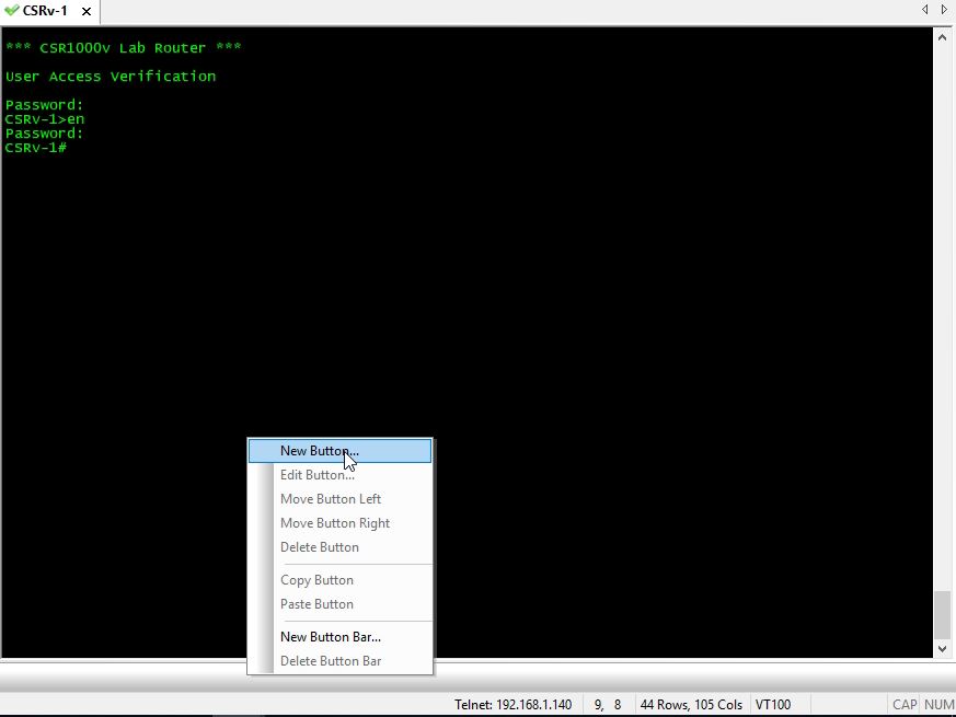
You can add a Button Bar in Secure CRT to send a string command in your SSH session. This will "automate" frequently typed commands to a Cisco device. To add a button, right-click at the bottom of the terminal screen > select Button Bar.

Alternatively, go to View > select Button Bar.

Select New Button.

Select Function: Send String > type a command String > optional: type a Label > click OK.


In newer versions of Secure CRT, you can choose the button color.

Notice there's a "break" in the output and had an invalid input. This typically happens when the output is very long such as the show version command output.


In order to avoid this, you should the include terminal length 0 command at the start of the string. Right-click on the button > select Edit Button. You can use a Notepad to edit strings and then copy/paste in Secure CRT.


Saturday, March 2, 2024

Cisco BGP neighbor shutdown Command

To administratively shutdown a BGP neighbor in a Cisco router, issue a neighbor <BGP PEER IP> shutdown command under the BGP routing process. This will stop the BGP route exchange with the BGP neighbor/peer and it's often useful when performing a maintenance such as policy change with the peer/upstream ISP.

R1#show run | sec router bgp

router bgp 64001

 bgp router-id 62.19.10.15

 bgp log-neighbor-changes

 no bgp default ipv4-unicast

 neighbor 62.19.10.16 remote-as 700

 neighbor 62.19.10.16 description ISP

 neighbor 62.19.10.16 password cisco123

 neighbor 62.19.10.16 update-source GigabitEthernet0/0

 neighbor 62.19.10.16 version 4


<OUTPUT TRUNCATED>


R1#configure terminal

Enter configuration commands, one per line.  End with CNTL/Z.

R1(config-router)#neighbor 62.19.10.16 ?

  ao                         TCP-AO authentication

  bmp-activate               Activate the BMP monitoring for a BGP peer

  cluster-id                 Configure Route-Reflector Cluster-id (peers may reset)

  description                Neighbor specific description

  disable-connected-check    one-hop away EBGP peer using loopback address

  dont-capability-negotiate  Send Capability parameters in Open

  ebgp-multihop              Allow EBGP neighbors not on directly connected networks

  fall-over                  session fall on peer route lost

  ha-mode                    high availability mode

  inherit                    Inherit a template

  local-as                   Specify a local-as number

  log-neighbor-changes       Log neighbor up/down and reset reason

  password                   Set a password

  path-attribute             BGP optional attribute filtering

  peer-group                 Member of the peer-group

  remote-as                  Specify a BGP neighbor

  shutdown                   Administratively shut down this neighbor

  timers                     BGP per neighbor timers

  transport                  Transport options

  ttl-security               BGP ttl security check

  update                     Modify update processing

  update-source              Source of routing updates

  version                    Set the BGP version to match a neighbor


R1(config-router)#neighbor 62.19.10.16 shutdown

R1(config-router)#end


R1#show run | sec router bgp

router bgp 64001

 bgp router-id 62.19.10.15

 bgp log-neighbor-changes

 no bgp default ipv4-unicast

 neighbor 62.19.10.16 remote-as 700

 neighbor 62.19.10.16 description ISP

 neighbor 62.19.10.16 shutdown

 neighbor 62.19.10.16 password cisco123

 neighbor 62.19.10.16 update-source GigabitEthernet0/0

 neighbor 62.19.10.16 version 4


<OUTPUT TRUNCATED>


R1#show ip bgp summary

BGP router identifier 62.19.10.15, local AS number 64001

BGP table version is 394500023, main routing table version 394500023

860025 network entries using 213286200 bytes of memory

1720036 path entries using 233924896 bytes of memory

431848/148584 BGP path/bestpath attribute entries using 120917440 bytes of memory

240343 BGP AS-PATH entries using 11369538 bytes of memory

25898 BGP community entries using 3703042 bytes of memory

0 BGP route-map cache entries using 0 bytes of memory

0 BGP filter-list cache entries using 0 bytes of memory

BGP using 583201116 total bytes of memory

BGP activity 19138181/18274056 prefixes, 156266333/154546297 paths, scan interval 60 secs


Neighbor        V           AS MsgRcvd MsgSent   TblVer  InQ OutQ Up/Down  State/PfxRcd

62.19.10.16     4          700       0       0        1    0    0 00:00:28 Idle (Admin)


R1#show ip bgp neighbor 62.19.10.16

BGP neighbor is 62.19.10.16,  remote AS 700, external link

 Description: ISP

 Administratively shut down

  BGP version 4, remote router ID 0.0.0.0

  BGP state = Idle, down for 00:00:43

  Neighbor sessions:

    0 active, is not multisession capable (disabled)

    Stateful switchover support enabled: NO

  Do log neighbor state changes (via global configuration)

  Default minimum time between advertisement runs is 30 seconds


<OUTPUT TRUNCATED>


To re-enable the BGP neighbor, just use the 'no' form of the said command.


R1#configure terminal

Enter configuration commands, one per line.  End with CNTL/Z.

R1(config)#router bgp 64001

R1(config-router)#no neighbor 62.19.10.16 shutdown

R1(config-router)#end


R1#show run | sec router bgp

router bgp 64001

 bgp router-id 62.19.10.15

 bgp log-neighbor-changes

 no bgp default ipv4-unicast

 neighbor 62.19.10.16 remote-as 700

 neighbor 62.19.10.16 description ISP

 neighbor 62.19.10.16 password cisco123

 neighbor 62.19.10.16 update-source GigabitEthernet0/0

 neighbor 62.19.10.16 version 4

 <OUTPUT TRUNCATED>


Friday, February 2, 2024

Cisco Switch VTP Version 3

The VLAN Trunking Protocol (VTP) version 3 is backwards compatible with version 2 but not with version 1. VTP version 3 supports Extended VLAN range (1006-4094), Private VLAN (PVLAN), Multiple Spanning Tree (MST), encrypt/hash VTP password and many more.

The main command for checking VTP info in a Cisco switch is show vtp status. The current VTP version is 1.

SW01#show vtp status

VTP Version capable             : 1 to 3

VTP version running             : 1

VTP Domain Name                 :

VTP Pruning Mode                : Disabled

VTP Traps Generation            : Disabled

Device ID                       : aabb.cc00.0200

Configuration last modified by 0.0.0.0 at 0-0-00 00:00:00

Local updater ID is 0.0.0.0 (no valid interface found)


Feature VLAN:

--------------

VTP Operating Mode                : Server

Maximum VLANs supported locally   : 1005

Number of existing VLANs          : 5

Configuration Revision            : 0

MD5 digest                        : 0x57 0xCD 0x40 0x65 0x63 0x59 0x47 0xBD

                                    0x56 0x9D 0x4A 0x3E 0xA5 0x69 0x35 0xBC


Before changing to VTP version 3, you'll need to set the VTP domain first.


SW01#configure terminal

Enter configuration commands, one per line.  End with CNTL/Z.

SW01(config)#vtp version ?

  <1-3>  Set the administrative domain VTP version number


SW01(config)#vtp version 3

Cannot set the version to 3 because domain name is not configured

SW01(config)#

SW01(config)#vtp domain LAB

Changing VTP domain name from NULL to LAB

SW01(config)#

SW01(config)#vtp version 3

SW01(config)#

SW01(config)#vlan 99

VTP VLAN configuration not allowed when device is not the primary server for vlan database.

SW01(config)#

SW01(config)#end


In order to add/create Layer 2 VLANs, set the switch to VTP Primary using the privilege EXEC command vtp primary.


SW01#vtp ?

  password  Set the password for the VTP administrative domain.

  primary   Make the system as the primary server

  pruning   Set the administrative domain to permit pruning.

  version   Set the adminstrative domain VTP version


SW01#vtp primary ?

  force  Do not check for conflicting devices

  mst    MST feature

  vlan   Vlan feature

  <cr>


SW01#vtp primary

This system is becoming primary server for feature vlan

No conflicting VTP3 devices found.

Do you want to continue? [confirm]

SW01#

*Jan 29 02:57:46.373: %SW_VLAN-4-VTP_PRIMARY_SERVER_CHG: aabb.cc00.0200 has become the primary server for the VLAN VTP feature


SW01#configure terminal

Enter configuration commands, one per line.  End with CNTL/Z.

SW01(config)#vlan 99

SW01(config-vlan)#name TEST

SW01(config-vlan)#end


SW01#show vtp status

VTP Version capable             : 1 to 3

VTP version running             : 3

VTP Domain Name                 : LAB

VTP Pruning Mode                : Disabled

VTP Traps Generation            : Disabled

Device ID                       : aabb.cc00.0200


Feature VLAN:

--------------

VTP Operating Mode                : Primary Server

Number of existing VLANs          : 6

Number of existing extended VLANs : 0

Maximum VLANs supported locally   : 4096

Configuration Revision            : 2

Primary ID                        : aabb.cc00.0200

Primary Description               : SW01

MD5 digest                        : 0x69 0x34 0x9F 0x61 0x0A 0xF0 0x29 0x1F

                                    0xAE 0xDB 0xFA 0x70 0xCA 0x10 0x50 0x35


Feature MST:

--------------

VTP Operating Mode                : Transparent


Feature UNKNOWN:

--------------

VTP Operating Mode                : Transparent


SW01#show vlan brief


VLAN Name                             Status    Ports

---- -------------------------------- --------- -------------------------------

1    default                          active    Et0/0, Et0/3, Et1/0, Et1/1

                                                Et1/2, Et1/3, Et2/0, Et2/1

                                                Et2/2, Et2/3, Et3/0, Et3/1

                                                Et3/2, Et3/3

99   TEST                             active   

1002 fddi-default                     act/unsup

1003 trcrf-default                    act/unsup

1004 fddinet-default                  act/unsup

1005 trbrf-default                    act/unsup


The VTP password is shown in plain text. In VTP version 3, you can "hide" or hash the password.

SW01#configure terminal

Enter configuration commands, one per line.  End with CNTL/Z.

SW01(config)#vtp password cisco123

Setting device VTP password to cisco123

SW01(config)#do show vtp password

VTP Password: cisco123


SW01(config)#vtp password ?

  WORD  The ascii password for the VTP administrative domain.


SW01(config)#vtp password cisco123 ?

  hidden  Set the VTP password hidden option

  secret  Specify the vtp password in encrypted form

  <cr>


SW01(config)#vtp password cisco123 hidden

Setting device VTP password 

SW01(config)#

SW01(config)#do sh vtp password         

VTP Password: DD9E88A11A75B21E42627A20F00FD980


If you're adding another switch, just copy/paste the hashed string and use the keyword secret.


SW02(config)#vtp password DD9E88A11A75B21E42627A20F00FD980 secret