Friday, November 14, 2014

Cisco 2900 Password Recovery via Ejecting Compact Flash (CF) Card

I was trying to factory reset a Cisco 2911 router which was deployed to one of our customer. I always do the password recovery by hitting the "Break" key to get into ROMmon mode and then change the config-register setting. I sometimes tend to perform this step a few times (due to multitasking) if I don't hit the Break key successfully.

This time I used an easy alternative method which is a sure way to get into ROMmon mode. We can also get into ROMmon mode by removing the Compact Flash (CF) card located at the back of the 2911 router. It's usually inserted on CF 0 slot located on the right-hand side.

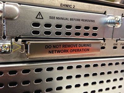
I used a flat head screwdriver to remove the metal cover. This is a good innovation on the ISR G2 router because the ejector on older (ISR G1, i.e. 2811) routers tends to break a lot of times (mine included) since it's exposed and made of plastic.


These are the steps to perform a password recovery or factory reset a 2911 router:


System Bootstrap, Version 15.0(1r)M16, RELEASE SOFTWARE (fc1)
Technical Support: http://www.cisco.com/techsupport
Copyright (c) 2012 by cisco Systems, Inc.

Total memory size = 512 MB - On-board = 512 MB, DIMM0 = 0 MB
CISCO2911/K9 platform with 524288 Kbytes of main memory
Main memory is configured to 72/-1(On-board/DIMM0) bit mode with ECC enabled


Readonly ROMMON initialized
Compact Flash0: Not present

System Bootstrap, Version 15.0(1r)M16, RELEASE SOFTWARE (fc1)
Technical Support: http://www.cisco.com/techsupport
Copyright (c) 2012 by cisco Systems, Inc.

Total memory size = 512 MB - On-board = 512 MB, DIMM0 = 0 MB
CISCO2911/K9 platform with 524288 Kbytes of main memory
Main memory is configured to 72/-1(On-board/DIMM0) bit mode with ECC enabled


Readonly ROMMON initialized
Compact Flash1: Not present

System Bootstrap, Version 15.0(1r)M16, RELEASE SOFTWARE (fc1)
Technical Support: http://www.cisco.com/techsupport
Copyright (c) 2012 by cisco Systems, Inc.

Total memory size = 512 MB - On-board = 512 MB, DIMM0 = 0 MB
CISCO2911/K9 platform with 524288 Kbytes of main memory
Main memory is configured to 72/-1(On-board/DIMM0) bit mode with ECC enabled


Readonly ROMMON initialized
Compact Flash0: Not present

System Bootstrap, Version 15.0(1r)M16, RELEASE SOFTWARE (fc1)
Technical Support: http://www.cisco.com/techsupport
Copyright (c) 2012 by cisco Systems, Inc.

Total memory size = 512 MB - On-board = 512 MB, DIMM0 = 0 MB
CISCO2911/K9 platform with 524288 Kbytes of main memory
Main memory is configured to 72/-1(On-board/DIMM0) bit mode with ECC enabled


Readonly ROMMON initialized
rommon 1 > confreg 0x2142     // BYPASS STARTUP CONFIG STORED IN FLASH; RE-INSERT CF CARD

You must reset or power cycle for new config to take effect
rommon 2 > reset

<OUTPUT TRUNCATED>

Router>enable
Router#copy startup-config running-config     // CHANGE ENABLE AND VTY PASSWORDS; OR ISSUE write erase
Destination filename [running-config]?

CUSTOMER#configure terminal
Enter configuration commands, one per line.  End with CNTL/Z.
CUSTOMER(config)#config-register ?    
  <0x0-0xFFFF>  Config register number

CUSTOMER(config)#config-register 0x2102    // DEFAULT CONFREG SETTING; NORMALLY LOAD IOS FROM FLASH AND LOAD THE STARTUP CONFIG
CUSTOMER(config)#end
CUSTOMER#write memory
Building configuration...


*Nov 13 10:22:47 ICT: %SYS-5-CONFIG_I: Configured from console by console[OK]
CUSTOMER#reload
Proceed with reload? [confirm]

<OUTPUT TRUNCATED>

Router>show version
Cisco IOS Software, C2900 Software (C2900-UNIVERSALK9-M), Version 15.2(4)M3, RELEASE SOFTWARE (fc2)
Technical Support: http://www.cisco.com/techsupport
Copyright (c) 1986-2013 by Cisco Systems, Inc.
Compiled Tue 26-Feb-13 03:42 by prod_rel_team

ROM: System Bootstrap, Version 15.0(1r)M16, RELEASE SOFTWARE (fc1)

Router uptime is 1 minute
System returned to ROM by reload at 10:27:31 ICT Thu Nov 13 2014
System image file is "flash0:c2900-universalk9-mz.SPA.152-4.M3.bin"
Last reload type: Normal Reload
Last reload reason: Reload Command


This product contains cryptographic features and is subject to United
States and local country laws governing import, export, transfer and
use. Delivery of Cisco cryptographic products does not imply
third-party authority to import, export, distribute or use encryption.
Importers, exporters, distributors and users are responsible for
compliance with U.S. and local country laws. By using this product you
agree to comply with applicable laws and regulations. If you are unable
to comply with U.S. and local laws, return this product immediately.

A summary of U.S. laws governing Cisco cryptographic products may be found at:
http://www.cisco.com/wwl/export/crypto/tool/stqrg.html

If you require further assistance please contact us by sending email to
export@cisco.com.

Cisco CISCO2911/K9 (revision 1.0) with 909312K/40960K bytes of memory.
Processor board ID FGL1728xxxx
3 Gigabit Ethernet interfaces
1 terminal line
1 Virtual Private Network (VPN) Module
DRAM configuration is 64 bits wide with parity enabled.
255K bytes of non-volatile configuration memory.
250880K bytes of ATA System CompactFlash 0 (Read/Write)


License Info:

License UDI:

-------------------------------------------------
Device#   PID                   SN
-------------------------------------------------
*0        CISCO2911/K9          FGL1728xxxx   


Technology Package License Information for Module:'c2900'

-----------------------------------------------------------------
Technology    Technology-package           Technology-package
              Current       Type           Next reboot 
------------------------------------------------------------------
ipbase        ipbasek9      Permanent      ipbasek9
security      securityk9    Permanent      securityk9
uc            uck9          Permanent      uck9
data          None          None           None

Configuration register is 0x2102

Saturday, November 1, 2014

My WD-40 Saves the Day

I mentioned on my last post that I picked up a couple of Cisco Compact Flash (CF) cards. I forgot to mention that I also picked up a Cisco 3560 8-port (C3560-8PC) switch in our warehouse's dumpster. There were some sticker or paint residue on top of it and I wanted to clean it off. I've read and tried using baby oil, vegetable and canola cooking oil but they weren't effective. I also read somewhere you could use mayonaise or peanut butter but I didn't go that far.

So I ended up using WD-40 and my cleaning went smoothly. I just bought a small bottle and sprayed it on the gooey area and left to absorb for a few seconds. I used a hard plastic card (used my Western Union ID card) to scrape the goo and wiped off with tissue. The WD-40 is also a nice cleaning agent for my Cisco gear. It makes them glossy again and doesn't affect the metal, plastic or paint on the device.


Before:

After:


My Cisco storage box:

Friday, October 24, 2014

Router IOS Upgrade via tftpdnld and format flash Command

There were some IT stuff that my company's warehouse got rid of not so long ago. I was lucky to have picked up a couple of Cisco 64 MB Compact Flash (CF) cards. So I tested them out and inserted them in one of my lab router to update its Internetwork Operating Software (IOS).

I've used the handy tftpdnld command in ROM Monitor (ROMmon) mode. I was able to get to ROMmon by booting up the router without its CF card. I also connected an RJ45 cable to port F0/0 (sometimes other ports doesn't work) on the 1841, set my laptop to 10.1.1.1/24 and ran a TFTP client. The commands in ROMmon mode are case sensitive.

rommon 1 > tftpdnld

Missing or illegal ip address for variable IP_ADDRESS
Illegal IP address.

usage: tftpdnld [-hr]
  Use this command for disaster recovery only to recover an image via TFTP.
  Monitor variables are used to set up parameters for the transfer.
  (Syntax: "VARIABLE_NAME=value" and use "set" to show current variables.)
  "ctrl-c" or "break" stops the transfer before flash erase begins.

  The following variables are REQUIRED to be set for tftpdnld:
            IP_ADDRESS: The IP address for this unit
        IP_SUBNET_MASK: The subnet mask for this unit
       DEFAULT_GATEWAY: The default gateway for this unit
           TFTP_SERVER: The IP address of the server to fetch from
             TFTP_FILE: The filename to fetch

  The following variables are OPTIONAL:
          TFTP_VERBOSE: Print setting. 0=quiet, 1=progress(default), 2=verbose
      TFTP_RETRY_COUNT: Retry count for ARP and TFTP (default=18)
          TFTP_TIMEOUT: Overall timeout of operation in seconds (default=7200)
         TFTP_CHECKSUM: Perform checksum test on image, 0=no, 1=yes (default=1)
               FE_PORT: 0= (default), 1
         FE_SPEED_MODE: 0=10/hdx, 1=10/fdx, 2=100/hdx, 3=100/fdx,
                        4=Auto (default)

  Command line options:
   -h: this help screen
   -r: do not write flash, load to DRAM only and launch image

rommon 1 > IP_ADDRESS=10.1.1.2    // I USED THE 10.x.x.x NETWORK TO AVOID CONFLICT WITH MY WIFI 192.168.1.0/24 SUBNET
rommon 2 > IP_SUBNET_MASK=255.255.255.0
rommon 3 > DEFAULT_GATEWAY=10.1.1.1
rommon 4 > TFTP_SERVER=10.1.1.1
rommon 5 > TFTP_FILE=c1841-adventerprisek9-mz.124-24.T2.bin
rommon 6 > tftpdnld    // NOT CASE SENSITIVE

          IP_ADDRESS: 10.1.1.2
      IP_SUBNET_MASK: 255.255.255.0
     DEFAULT_GATEWAY: 10.1.1.1
         TFTP_SERVER: 10.1.1.1
           TFTP_FILE: c1841-adventerprisek9-mz.124-24.T2.bin
        TFTP_MACADDR: 00:0a:b8:f8:83:92
        TFTP_VERBOSE: Progress
    TFTP_RETRY_COUNT: 18
        TFTP_TIMEOUT: 7200
       TFTP_CHECKSUM: Yes
             FE_PORT: 0
       FE_SPEED_MODE: Auto Detect

Invoke this command for disaster recovery only.
WARNING: all existing data in all partitions on flash will be lost!
Do you wish to continue? y/n:  [n]:  y
.
Receiving c1841-adventerprisek9-mz.124-24.T2.bin from 10.1.1.1 !!!!!!!!!!!!!!!!!!!!!!!!!!!!!!!!!!!!!!!!!!!!!!!!!!!!!!!!!!!!!!!!!!!!!!!!!!!!!!!!!!!!!!!!!!!!!!!!!!!!!!!!!!!!!!!!!!!!!!!!!!!!!!!!!!!!!!!!!!!!!!!!!!!!!!!!!!!!!!!!!!!!!!!!!!!!!!!!!!!!!!!!!!!!!!!!!!!!!!!!!!!!

<OUTPUT TRUNCATED>

!!!!!!!!!!!!!!!!!!!!!!!!!!!!!!!!!!!!!!!!!!!!!!!!!!!!!!!!!!!!!!!!!!!!!!!!!!!!!!!!!!!!!!!!.................. [TIMED OUT]
TFTP: Operation terminated.


For some reason the TFTP timed out in the end. So I boot up my 1841 with a working IOS and saw the CF that I picked up wasn't formatted properly. I used the format flash: command to format the CF card and in order to be compatible with the router.


R1#show flash
Unformatted Partition, please format it.

R1#
Unknown file system detected.
Use format command to format the card as DOS File System.

R1#format ?
  flash:  Filesystem to be formatted

R1#format flash: ?
  <cr>

R1#format flash:
Format operation may take a while. Continue? [confirm]
Format operation will destroy all data in "flash:".  Continue? [confirm]
Enter volume ID (up to 64 chars)[default flash:]:

Primary Partition created...Size 61 MB

Drive communication & 1st Sector Write OK...
Writing Monlib sectors....
Monlib write complete

Format: All system sectors written. OK...

Format: Total sectors in formatted partition: 125408
Format: Total bytes in formatted partition: 64208896
Format: Operation completed successfully.

Format of flash: complete    // JUST TOOK A FEW SECONDS TO RE-FORMAT


Since I'm in privileged EXEC mode on the router, I can perform the IOS upgrade via the copy tftp flash command.

R1#configure terminal
Enter configuration commands, one per line.  End with CNTL/Z.
R1(config)#interface fastethernet0/0
R1(config-if)#ip address 10.1.1.1 255.255.255.0
R1(config-if)#no shutdown
*Oct 25 06:23:03.643: %LINK-3-UPDOWN: Interface FastEthernet0/0, changed state to up
*Oct 25 06:23:04.643: %LINEPROTO-5-UPDOWN: Line protocol on Interface FastEthernet0/0, changed state to up
R1(config-if)#end
R1#
*Oct 25 06:23:29.107: %SYS-5-CONFIG_I: Configured from console by console
R1#copy tftp://10.1.1.1/c1841-adventerprisek9-mz.124-24.T2.bin flash:
Destination filename [c1841-adventerprisek9-mz.124-24.T2.bin]?
Accessing tftp://10.1.1.1/c1841-adventerprisek9-mz.124-24.T2.bin...
Loading c1841-adventerprisek9-mz.124-24.T2.bin from 10.1.1.1 (via FastEthernet0/0): !!!!!!!!!!!!!!!!!!!!!!!!!!!!!!!!!!!!!!!!!!!!!!!!!!!!!!!!!!!!!!!!!!!!!!!!!!!!!!!!!!!!!!!!!!!!!!!!!!!!!!!!!!!!!!!!!!!!!!!!!!!!!!!!!!!!!!!!!!!!!!!!!!!!!!!!!!!!!!!
[OK - 40529832 bytes]

40529832 bytes copied in 183.628 secs (220717 bytes/sec)

R1#reload

System configuration has been modified. Save? [yes/no]: n
Proceed with reload? [confirm]

*Oct 25 06:28:17.659: %SYS-5-RELOAD: Reload requested  by console. Reload Reason: Reload Command.

<OUTPUT TRUNCATED>

R1>enable
R1#dir    // ALTERNATIVE TO show flash
Directory of flash:/

    1  -rw-    40529832  Oct 25 2014 06:26:48 +00:00  c1841-adventerprisek9-mz.124-24.T2.bin

64004096 bytes total (23474176 bytes free)

R1#show version | include IOS
Cisco IOS Software, 1841 Software (C1841-ADVENTERPRISEK9-M), Version 12.4(24)T2, RELEASE SOFTWARE (fc2)

Saturday, October 18, 2014

CCNP ROUTE Lab Equipment

I got a little sidetracked from my CCNP Security journey and I'll be taking up CCDP (hopefully to also add CompTIA Security+) while waiting for the new books to be officially released next year. I only got SITCS left and it's rumored that the Cisco press Official Certification Guide (OCG) would be released sometime in May 2015.

I already got CCNP SWITCH, which in my opinion was the easiest exam among the three, back in 2011 in order to extend my CCNP. I would also need to take ROUTE and ARCH. The CCNP exams will be updated to version 2 and the last day to sit for ROUTE, SWITCH and TSHOOT version 1 will be on January 29, 2015. Cisco hasn't changed yet their exam for CCDP ARCH 642-874 as of this writing.

I'm done reading the ROUTE OCG and was doing some labs. I've used the CCNP ROUTE Lab Manual which is free on the Internet. My lab consists of  a 871w router (not shown in the pic) for my wireless access, 2511 router for my terminal server, a 3560 switch, 3x 1841 ISR for my branch/spoke routers and a 2811 for my hub router or as a frame relay switch.


These are the screenshots on how to use my Terminal Server menu options.


Aside from the "menu" options on my Terminal Server, a Telnet session can be opened by typing the hostname under privileged EXEC mode.


I mentioned on my last post that I'll be using my 871w for my wifi and connect it to the AUI adapter on the 2511 so that I could conveniently access to my lab devices using wireless (with an iPad). The wifi access on my 871w together with the 2511 Terminal Server helps me perform my labs easier. It also saves my home users from screaming there's no Internet access :)


Here's the complete working config on my Terminal Server.

2511-TS#sh run
Building configuration...

Current configuration : 2700 bytes
!
version 12.2
service timestamps debug datetime msec
service timestamps log datetime msec
no service password-encryption
service udp-small-servers
service tcp-small-servers
!
hostname 2511-TS
!
logging queue-limit 100
enable password cisco
!
username cisco privilege 15 password 0 cisco
ip subnet-zero
ip host sw 2002 1.1.1.1
ip host fr 2001 1.1.1.1
ip host r3 2005 1.1.1.1
ip host r2 2004 1.1.1.1
ip host r1 2003 1.1.1.1
!
!
!
!
interface Loopback0
 ip address 1.1.1.1 255.255.255.255
!
interface Ethernet0
 description TRUNK TO 871W
 ip address 192.168.1.2 255.255.255.0
 no ip route-cache
 no ip mroute-cache
!
interface Serial0
 no ip address
 no ip route-cache
 no ip mroute-cache
 shutdown
 no fair-queue
!
interface Serial1
 no ip address
 no ip route-cache
 no ip mroute-cache
 shutdown
!
no ip http server
ip classless
!
!
!
!
menu TS title ^C
+---------------------------------------------------+
|  John Lagura's CCNP ROUTE Lab Terminal Server     |
|                                                   |
| To exit a device, use CTRL+SHIFT+6 then press x   |
+---------------------------------------------------+
^C
menu TS prompt ^C Make a selection: ^C
menu TS text 1 Connect to Lab rack 2811- Frame Relay Switch
menu TS command 1 resume fr /connect telnet fr
menu TS text 2 Connect to Lab rack 3560 - SW1
menu TS command 2 resume sw /connect telnet sw
menu TS text 3 Connect to Lab rack 1841 - R1
menu TS command 3 resume r1 /connect telnet r1
menu TS text 4 Connect to Lab rack 1841 - R2
menu TS command 4 resume r2 /connect telnet r2
menu TS text 5 Connect to Lab rack 1841 - R3
menu TS command 5 resume r3 /connect telnet r3
menu TS command c3 c3
menu TS command c4 c4
menu TS command c5 c5
menu TS command c1 c1
menu TS command c2 c2
menu TS text s Show all established sessions
menu TS command s show sessions
menu TS options s pause
menu TS text e Exit Menu
menu TS command e menu-exit
menu TS text c# Clear the session by number, example: c1
menu TS text q Quit TS session
menu TS command q quit
menu TS clear-screen
menu TS line-mode
!
banner login ^C
+--------------------------------------------------------------+
| This equipment is privately owned and monitored.             |
| Disconnect immediately if you are not an authorized user.    |
+--------------------------------------------------------------+
^C
alias exec c1 disconnect fr
alias exec c2 disconnect sw
alias exec c3 disconnect r1
alias exec c4 disconnect r2
alias exec c5 disconnect r3
!
line con 0
 logging synchronous
line 1 16
 exec-timeout 0 0
 no flush-at-activation
 no exec
 transport input telnet
line aux 0
 transport input all
line vty 0 4
 password cisco
 login local
 autocommand  menu TS
!
end

Sunday, September 14, 2014

Cisco ISR G2 Router Serial Number

It's funny, I've been working with ISR G2 routers for quite some time now but I recently found out there's another way of checking its serial number. Aside from the serial number indicated on the carton box and beneath the router, there's a pull-out label found at the back of the router. It's right in the middle of the EHWIC0 and the secondary power supply module.

This is a convenient way of checking out the serial number without having to go to CLI or if there's another device rack mounted beneath it. On older ISR router, the serial number sticker is usually found behind the router and is above the FE0/1 port.


Here's a sample of the flip serial number tag on a Cisco 2911 ISR G2 router.


Friday, September 5, 2014

Cisco 3900 ISR G2 Power Supply and Fan Module Swap

I got an escalation from our NOC a couple of weeks back saying one of our core router had an alarm. When I checked the logs, I noticed the CPU temperature was high, one of the the power supply and the fan had failed.

Aug  4 00:25:39.937 UTC: %ENVMON-4-ONE_FAN_LOW_RPM: Warning: Fan 2 is running at low RPM.  Rotation speed is now high for all other fans.  Fan Tray replacement is recommended.

Aug  4 00:28:10.119 UTC: %ENVMON-1-CPU_WARNING_OVERTEMP: Warning: CPU temperature 101C exceeds threshold 95C.  Please resolve system cooling immediately to prevent system damage


3945#show environment
SYSTEM POWER SUPPLY STATUS
==========================
 Internal Power Supply 1 Type: AC
 Internal Power Supply 1 12V Output Status: Normal

 Internal Power Supply 2 Type: Absent 

SYSTEM FAN STATUS
=================
 Fan Rotation Alert: Total 1 Fan Low RPM 
 Fan 1 OK, Maximum speed setting
 Fan 2 Low RPM   
 Fan 3 OK, Maximum speed setting
 Fan 4 OK, Maximum speed setting
 Fan 5 OK, Maximum speed setting

SYSTEM TEMPERATURE STATUS
=========================
 Intake Left temperature: 36 Celsius, Normal
 Intake Right temperature: 29 Celsius, Normal
 Exhaust Right temperature: 44 Celsius, Normal
 Exhaust Left temperature: 49 Celsius, Normal
 CPU temperature: 106 Celsius, Over-Temperature  
 Power Supply Unit 1 temperature: 40 Celsius, Normal

REAL TIME CLOCK BATTERY STATUS
==============================
 Battery OK (checked at power up)

SYSTEM POWER
===============
 Motherboard Components Power consumption = 79.0 W
 Total System Power consumption is: 79.0 W

 Environmental information last updated 00:00:07 ago


I immediately contacted Cisco TAC and asked for an RMA.

The power supply (PWR-3900-AC) has screws on the sides which helps in pulling out from the router's chassis.


These are front and back view of the fan module/assembly (3900-FANASSY). The RMA comes with a new faceplate.


According to Cisco, these modules are hot-swappable so you don't need to turn off the chassis. You also got at least two minutes to do the swap in order to avoid further CPU overheating. When I removed the router's faceplate, I've observed that all five fans weren't rotating and blown air was warm. This issue has been going for at least 3 days before I swapped the new modules. Good thing nothing melted inside :)


When you removed the fan assembly, you would see two power supplies.


Aug  7 13:59:32.305 UTC: %ENVMON-2-FAN_TRAY_MISSING: Critical Warning: Fan tray was removed.  Please re-insert fan tray to prevent system from overheating.
Aug  7 14:00:32.380 UTC: %ENVMON-1-POWER_WARNING: : Internal Power Supply Unit 2  AC or DC input source has been removed.
Aug  7 14:01:02.416 UTC: %ENVMON-5-POWER_NOTICE: : Internal Power Supply Unit 2  12V is UP %ENVMON-5-POWER_NOTICE: : Internal Power Supply Unit 2  12V is UP
Aug  7 14:02:32.683 UTC: %ENVMON-6-CPU_TEMP_OK: CPU temperature normal
Aug  7 14:02:32.683 UTC: %ENVMON-6-FAN_TRAY_OK: Fan tray is detected.


3945#show inventory

<OUTPUT TRUNCATED>

NAME: "C3900 AC Power Supply 1", DESCR: "C3900 AC Power Supply 1"
PID: PWR-3900-AC       , VID: V03 , SN: QCS1726abcde

NAME: "C3900 AC Power Supply 2", DESCR: "C3900 AC Power Supply 2"
PID: PWR-3900-AC       , VID: V04 , SN: QCS173abcde


3945#show environment
SYSTEM POWER SUPPLY STATUS
==========================
 Internal Power Supply 1 Type: AC
 Internal Power Supply 1 12V Output Status: Normal

 Internal Power Supply 2 Type: AC
 Internal Power Supply 2 12V Output Status: Normal


SYSTEM FAN STATUS
=================
 Fan 1 OK, Low speed setting
 Fan 2 OK, Low speed setting
 Fan 3 OK, Low speed setting
 Fan 4 OK, Low speed setting
 Fan 5 OK, Low speed setting

SYSTEM TEMPERATURE STATUS
=========================
 Intake Left temperature: 20 Celsius, Normal
 Intake Right temperature: 19 Celsius, Normal
 Exhaust Right temperature: 20 Celsius, Normal
 Exhaust Left temperature: 22 Celsius, Normal
 CPU temperature: 44 Celsius, Normal
 Power Supply Unit 1 temperature: 21 Celsius, Normal
 Power Supply Unit 2 temperature: 24 Celsius, Normal

REAL TIME CLOCK BATTERY STATUS
==============================
 Battery OK (checked at power up)

SYSTEM POWER
===============
 Motherboard Components Power consumption = 123.6 W
 Total System Power consumption is: 123.6 W

 Environmental information last updated 00:00:10 ago

Saturday, August 23, 2014

Cisco 2960S FlexStack Module and Cable

I was asked to stack some few Cisco 2960S switches for a site.


You can stack 2 or more switches (depending on the switch platform) using the Cisco FlexStack module and cable. The StackWise technology is used by Cisco 3750 switches.


Switch(config)#switch ?
  <1-4>  Switch Number   // 2960S CAN STACK UP TO 4 SWITCHES

Switch(config)#switch 1 ?
  priority   Set the priority of the specified switch
  provision  Configure Switch provision / offline config
  renumber   Renumber the specified switch number

Switch(config)#switch 1 priority ?
  <1-15>  Switch Priority

Switch(config)#switch 1 priority 15
Changing the Switch Priority of Switch Number 1 to 15
Do you want to continue?[confirm]
New Priority has been set successfully

Switch(config)#switch 2 priority 12   
There is no switch number 2 in the stack   // CAN ONLY ACTIVATE THIS COMMAND ONCE FLEXSTACK MODULE/CABLE IS CONNECTED

Switch(config)#switch 3 priority 10
There is no switch number 3 in the stack

Switch(config)#switch 2 priority 12
Changing the Switch Priority of Switch Number 2 to 12
Do you want to continue?[confirm]
New Priority has been set successfully

Switch(config)#switch 3 priority 10
Changing the Switch Priority of Switch Number 3 to 10
Do you want to continue?[confirm]
New Priority has been set successfully


You can pre-configure ports on member switches using the switch x provision y command. You can stack a Cisco 2960S 24-port together with a 48-port switch.

I needed this command since the VLANs and ports on our 2960S switches were already configured. Once stacking is done and switches are rebooted, our VLAN 1 management IP address on member switches were gone. The config on the master switch remained intact.

Switch(config)#switch 2 provision ?
  ws-c2960s-24pd-l   provision a Catalyst 2960s switch with 24GPwr+2SFP+ interfaces
  ws-c2960s-24ps-l   provision a Catalyst 2960s switch with 24GPwr+4SFP interfaces
  ws-c2960s-24td-l   provision a Catalyst 2960s switch with 24G+2SFP+ interfaces
  ws-c2960s-24ts-l   provision a Catalyst 2960s switch with 24G+4SFP interfaces
  ws-c2960s-24ts-s   provision a Catalyst 2960s switch with 24G+2SFP interfaces
  ws-c2960s-48fpd-l  provision a Catalyst 2960s switch with 48GPwr+2SFP+ interfaces
  ws-c2960s-48fps-l  provision a Catalyst 2960s switch with 48GPwr+4SFP interfaces
  ws-c2960s-48lpd-l  provision a Catalyst 2960s switch with 48GPwr+2SFP+ interfaces
  ws-c2960s-48lps-l  provision a Catalyst 2960s switch with 48GPwr+4SFP interfaces
  ws-c2960s-48td-l   provision a Catalyst 2960s switch with 48G+2SFP+ interfaces
  ws-c2960s-48ts-l   provision a Catalyst 2960s switch with 48G+4SFP interfaces
  ws-c2960s-48ts-s   provision a Catalyst 2960s switch with 48G+2SFP interfaces

Switch(config)#switch 2 provision ws-c2960s-24ps-l
Switch(config)#interface range GigabitEthernet2/0/1-24     // SWITCH 2; TAKE NOTE OF THE MODULE NUMBER (IN BOLD)
Switch(config-if)#switchport access vlan 110
Switch(config-if)#switchport mode access
Switch(config-if)#spanning-tree portfast

Switch(config)#switch 3 provision ws-c2960s-24ps-l
Switch(config)#interface range GigabitEthernet3/0/1-24    // SWITCH 3
Switch(config-if)#switchport access vlan 110
Switch(config-if)#switchport mode access
Switch(config-if)#spanning-tree portfast


Here are some useful show commands:

Switch#show switch ?
  <1-4>        Switch Number
  detail       show detailed information about the stack ring
  neighbors    show each switch's neighbors
  stack-ports  show the status of the stack ports
  stack-ring   show stack ring
  |            Output modifiers
  <cr>

Switch#show switch detail
Switch/Stack Mac Address : 6c9c.ed9d.g200
                                           H/W   Current
Switch#  Role   Mac Address     Priority Version  State
----------------------------------------------------------
*1       Master 6c9c.ed9d.g200     15     1       Ready            //  BOOT UP MASTER SWITCH FIRST AND THEN BOOT UP MEMBER SWITCHES ACCORDINGLY
 2       Member 6c9c.edc2.4300    12      1       Ready              
 3       Member 2c36.f85e.6e00     10      1       Ready             
         Stack Port Status             Neighbors    
Switch#  Port 1     Port 2           Port 1   Port 2
--------------------------------------------------------
  1        Ok         Ok                2        3
  2        Ok         Ok                1        3
  3        Ok         Ok                2        1

Switch#show switch neighbor
  Switch #    Port 1       Port 2
  --------    ------       ------
      1         2             3 
      2         1             3 
      3         2             1 

Switch#show switch stack-ports
  Switch #    Port 1       Port 2
  --------    ------       ------
    1           Ok           Ok  
    2           Ok           Ok  
    3           Ok           Ok  

Switch#show switch stack-ring ?
  activity  show stack ring activity
  speed     show stack ring speed

Switch#show switch stack-ring speed  

Stack Ring Speed        : 10G     // AGGREGATED BACKPLANE BANDWIDTH
Stack Ring Configuration: Full
Stack Ring Protocol     : FlexStack   // YOU'LL SEE STACKWISE ON 3750

Switch#show switch

Switch/Stack Mac Address : 6c9c.ed9d.g200
                                           H/W   Current
Switch#  Role   Mac Address     Priority Version  State
----------------------------------------------------------
*1       Master 6c9c.ed9d.g200     15     1       Ready              
 2       Member 6c9c.edc2.4300    12      1       Ready              
 3       Member 2c36.f85e.6e00     10      1       Ready 

Switch#show switch stack-port
  Switch #    Port 1       Port 2
  --------    ------       ------
    1           Ok           Ok  
    2           Ok           Ok  
    3           Ok           Ok  

Switch#show switch detail       
Switch/Stack Mac Address : 6c9c.ed9d.g200
                                           H/W   Current
Switch#  Role   Mac Address     Priority Version  State
----------------------------------------------------------
*1       Master 6c9c.ed9d.g200     15     1       Ready              
 2       Member 6c9c.edc2.4300    12      1       Ready              
 3       Member 2c36.f85e.6e00     10      1       Ready              

         Stack Port Status             Neighbors    
Switch#  Port 1     Port 2           Port 1   Port 2
--------------------------------------------------------
  1        Ok         Ok                2        3
  2        Ok         Ok                1        3
  3        Ok         Ok                2        1